- On source machine goto SMC->DAServer Manager->Default Group->local->Archestra.[DA Server Manager Name].[x]->Right Click On Configuration->Click Archive Configuration Set
- Give a meaningful name to the configuration set. An example would be "DASABCIP_10_9_2013". DASABCIP indicates which DAServer it is and 10_9_2013 indicates the date.
- Copy the configuration set from the source machine to media like a flash drive. The configuration set can be found in this location:
C:\ProgramData\Wonderware\DAServer\[DA Server Name]\[Configuration Set Name].aaCFG - The file just copied to media needs to be copied to the destination machine. Copy it to the same location it was copied from in Step 3.
- Deactivate the DAServer on the destination machine you want to restore the configuration set to.
- Right click on configuration like in Step 1. Then select "Use Another Configuration Set" and select the name you gave the configuration set in Step 2.
- Activate the DAServer
Wednesday, October 9, 2013
Moving DA Server Configuration
It is desirable to move a DA Server configuration from one computer to another via a file. This avoids the process of moving the configuration over by simply looking at the original DA Server. The risk of a manual move is that a configuration will be missed. You would then by faced with all of the challenges of integrating a DA Server with a device, leading to hours of work being lost. To avoid the risk of losing hours of work follow the simple steps below.
Friday, September 27, 2013
Trend Live Mode Refresh Interval
To reduce load on your Historian
server, change your live trend’s refresh interval. By default the live
trend will refresh itself every 1 second. Generally every 5 seconds will
be satisfactory. Just right click on your trend area and select
properties.
The refresh interval setting is
the first one on the “General” tab.
Wednesday, August 28, 2013
Serial to Ethernet Adapter
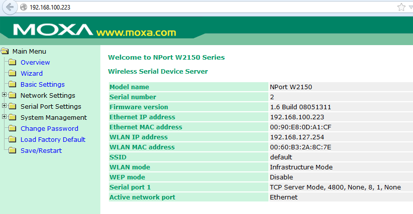
Many devices today still utilize serial ports for their primary interface. As Ethernet becomes more prevalent, it makes more sense to access legacy serial devices via this newer copper medium instead of expensive replacement. Moxa features many serial device servers which give Ethernet network connectivity to RS-232, 422, and 485 serial networks. Here's how to setup a Moxa NPort W2150.
Out of the box, this unit has a default IP address listed on the back. It features a built-in web server for configuring the IP address and serial port baud rate.
Lastly, download the Moxa NPort Com Port Driver. This driver dynamically finds each Moxa NPort and creates each respective com port on the PC.
Monday, July 29, 2013
Time Sync
Computer clocks don’t keep perfect time and tend to
drift. Since Wonderware Software
products are real-time systems it is important to keep the time correct to
avoid problems like data loss, incorrect data, and a variety of other problems. Such problems can be prevented by
implementing a time sync strategy.
There is a wide range of time sync strategies ranging from
enabling the domain controller’s time sync feature to relying on a feature of Historian
that is on by default. The one strategy
that stands out from the crowd is using a command line program called net time. It is the simplest to implement and works
better than the rest.
Implementing net
time is as simple as creating a Windows Scheduled Task to run the
command “NET TIME \\Historian /SET /YES” every
hour on all control system PCs except the PC selected to be the time
master. The time master PC should sync
to an atomic clock either through the Internet or an NTP time server available
on the LAN. If there is a Historian in
the system it is the preferred time master.
For screenshots on implementing net
time refer to Wonderware Tech Note 882.
If you are using System Platform it would be good to
consider implementing net time inside
of an object. The advantage is
maintenance. A small problem of having a
Windows Scheduled Task is when replacing the PC years later the Windows
Scheduled Task might be forgotten and not migrated to the new PC. The Windows Scheduled Task isn’t remembered
again until there is a problem with time synchronization and it has to be
troubleshot/re-implemented. This problem
can be avoided by implement net time inside a platform object, this way it is
automatically deployed to the computer.
Even the potential problem of the time master’s computer name changing
could be dealt with by doing some engineering. For example, you could place an
attribute on the platform called “TimeMasterName” and use that when calling net time.
It is important to turn off other time sync tools when
implementing net time. When multiple time sync tools are on they
tend to conflict. Below is the list of
commonly used time sync tools on systems.
Exactly how to disable them varies between versions, but a quick Google search
can look up disabling methods.
- · Windows Automatic Time Sync to Internet
- · VMWare’s Time Sync
- · Hyper-V’s Time Sync
- · Historian’s SuiteLink Time Sync (found in the system parameters)
- · The Domain Controller’s Automatic Time Sync (off by default)
Helpful Links
Wonderware Tech Note 882 on using net time. Note that it isn't necessary to make a batch file like the tech note does, a windows scheduled task can run net time commands without a batch file: https://wdnresource.wonderware.com/support/kbcd/html/1/t002685.htm
Microsoft article for Synchronizing to an atomic clock: http://www.microsoft.com/resources/documentation/windows/xp/all/proddocs/en-us/windows_date_it_overview.mspx?mfr=true
Labels:
Historian,
net time,
System Platorm,
time sync,
Wonderware
Wednesday, June 26, 2013
Horner Controlling a Stepper Drive
Horner features many HMIs that include I/O. Today, we're using an XL4 which is equipped with two high speed digital outputs for two axis of motion. Cscape, Horner's free programming software, configures the output between the options of PWM, high speed counter output, or stepper. In our case, we just want a typical stepper for our stepper drive.
This will allocate two regions of variables. AQ421 through AQ440 for analog outputs and I1617 through I1620 for digital inputs. The analog outputs are set points for both high speed outputs.
Let's look at just stepper 1 axis. Parameters start/run frequency and acceleration/run/deceleration count quantify our move profile. The only required parameters however are run frequency and run count. The others can remain zero.
Finally, set Q1 to true and Q1 will output the pulse train at the requested frequency and count. In this example, the drive is set to 3200 counts per rev and it will move at 15kHz. After the move is done, I1617 becomes true representing move complete. If bad values are used in the move profile for axis one, I1618 will be a value of 1.
What if you want to command direction? There are several more digital outputs you can use to command the direction bit on a stepper drive.
What if you want to jog the drive? Make the value of run count a very large number like 4 billion and reset Q1 when you desire to stop.
This will allocate two regions of variables. AQ421 through AQ440 for analog outputs and I1617 through I1620 for digital inputs. The analog outputs are set points for both high speed outputs.
Let's look at just stepper 1 axis. Parameters start/run frequency and acceleration/run/deceleration count quantify our move profile. The only required parameters however are run frequency and run count. The others can remain zero.
| Register | Stepper | Value |
| %AQ421 | Start Frequency | 0 |
| %AQ423 | Run Frequency | 15000 |
| %AQ425 | Acceleration Count | 0 |
| %AQ427 | Run Count | 3200 |
| %AQ429 | Deceleration Count | 0 |
Finally, set Q1 to true and Q1 will output the pulse train at the requested frequency and count. In this example, the drive is set to 3200 counts per rev and it will move at 15kHz. After the move is done, I1617 becomes true representing move complete. If bad values are used in the move profile for axis one, I1618 will be a value of 1.
What if you want to command direction? There are several more digital outputs you can use to command the direction bit on a stepper drive.
What if you want to jog the drive? Make the value of run count a very large number like 4 billion and reset Q1 when you desire to stop.
Monday, April 29, 2013
Decrease your Security Risk with GE QuickPanels
Decrease your security risk by giving certain users privileges. GE's series of QuickPanel HMIs use security to do just this. Here is how to configure and implement security on QuickPanels.
The act of configuring users is done during the runtime. Typically this means downloading and running on the QuickPanel itself but you can simulate the project on the PC before downloading. Click on the target within Machine Edition and enable the Simulate property.
Next, create/edit a panel and add two buttons anywhere. Double click one button to give a touch animation of
Double click the other button and give it a Touch animation with a script. You'll be using the
Now download the project and run. The target has been set to simulate so it should run on your local PC. Open the panel you've made and you'll see the two buttons we placed. Click the first button to trigger the logon dialogue. The default credential is:
After logging in, click on the second button to trigger the EditUserList dialogue. This window is where we create new users,access levels, and permissions.
At this point, security has been configured but it hasn't been implemented. Simply hide objects in all your panels by their Visibility Animation. Objects can be visible based on user or access level as shown below.
The act of configuring users is done during the runtime. Typically this means downloading and running on the QuickPanel itself but you can simulate the project on the PC before downloading. Click on the target within Machine Edition and enable the Simulate property.
Next, create/edit a panel and add two buttons anywhere. Double click one button to give a touch animation of
Logon.Double click the other button and give it a Touch animation with a script. You'll be using the
EditUserList command which can be found by right clicking in the script body.Now download the project and run. The target has been set to simulate so it should run on your local PC. Open the panel you've made and you'll see the two buttons we placed. Click the first button to trigger the logon dialogue. The default credential is:
username: master
password: controlAfter logging in, click on the second button to trigger the EditUserList dialogue. This window is where we create new users,access levels, and permissions.
At this point, security has been configured but it hasn't been implemented. Simply hide objects in all your panels by their Visibility Animation. Objects can be visible based on user or access level as shown below.
Wednesday, April 3, 2013
Use a web browser on ABB drives!
The FENA-01 Ethernet module for ABB drives can be reached through a web browser!
You will have access to 3 major sections of information.
Section 1: Status
This will show all of the important facts about the Ethernet module like software version, MAC and serial number.

Section 2: Configuration This will show all of the parameters needed to configure your Ethernet module to talk to your control system via EtherNet IP, Modbus TCP or ProfiNET.

Section 3: Support This section give you links to find important information like manuals and EDS files.

*Note: This is not a webpage that will show all of the parameters in the drive. It will only show Ethernet card related parameters.
- Using the keypad, enter a valid IP address in Group 51, Parameters 5105 through 5108.
- Using the keypad, enter a valid subnet mask like 255.255.255.0 which shows up as option 24 in Parameter 5109
- Parameter 51.27, Edit, Refresh to perform a parameter refresh or cycle power to the drive.
- Connect the drive to the same network as your PC and type the IP address into the address bar of your favorite browser.
You will have access to 3 major sections of information.
Section 1: Status
This will show all of the important facts about the Ethernet module like software version, MAC and serial number.

Section 2: Configuration This will show all of the parameters needed to configure your Ethernet module to talk to your control system via EtherNet IP, Modbus TCP or ProfiNET.

Section 3: Support This section give you links to find important information like manuals and EDS files.

*Note: This is not a webpage that will show all of the parameters in the drive. It will only show Ethernet card related parameters.
Labels:
ABB Drives,
FENA - 01 Ethernet module,
IP address,
web browser
Subscribe to:
Posts (Atom)