Tuesday, January 22, 2013

Manage EIP Traffic with No Configuration!

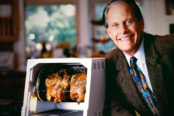
Moxa now has a version of their managed switch that has IGMP snooping enabled out of the box. This means that you can install this switch and manage that pesky EIP traffic without ever logging on to the switch. As inventor Ron Popeil says, "Set it and forget it"!
Some Moxa switch models are available with a -EIP model number. The difference between an EIP and a non-EIP switch is a configuration setting. The EIP models are factory configured for IGMP snooping.

Non-EIP

EIP

Firmware in both switches is the same. Both will forward EIP traffic. Both can be accessed via an Allen Bradley ControlLogix add-on instruction. The part number difference is only to enable IGMP snooping by default. The non-EIP switch can be configured to be a -EIP switch by making the configuration change above. Note: one switch in the network must be enabled as the Querier.

Thursday, January 3, 2013

Prepare Windows 7 for Wonderware Products

Installing Wonderware products to a computer has gotten far easier with the new one-disk install. There are a few things, however, the OS needs set as a best practice before installation.

Step 1 
Disable Data Execution Prevention: bcdedit.exe /set {current} nx AlwaysOff

Step 2 
Disable User Account Control: Control Panel, User Accounts, User Account Control, and lower the slider to the bottom. This will require a computer restart.
Step 3 
Firewalls can keep a computer safe from intrusions. They also hinder Wonderware communications if left with default settings. Either shut your firewall completely off or add a series of exceptions:

InTouch
  • slssvc.exe
  • wm.exe
InSQL or Historian
  • InSQLData.exe
  • InSQLConfig.exe
  • InSQLSCM.exe
  • InSQLRet.exe
  • SQLServr.exe
General Ports
  • 445 tcp
  • 1434 udp
  • 1433 tcp
  • 135 tcp
  • 102 DAS SI Direct
  • 502 DAS MBTCP
  • 2221 DAS ABTCP
  • 2222 DAS ABTCP
  • 2223 DAS ABTCP
  • 5413 S/L DA Servers
  • 44818 DASABCIP
For more details, visit the Security Settings for Wonderware Products pdf.
Now you're ready to begin Wonderware installation.

Wednesday, November 28, 2012

Interact for Windows 7

The release of Windows 7 has left most computer manufacturers with little choice but to abandon XP and include 7 instead. If your 3rd party software isn't ready for this then you're left with very few options. Parker's latest version of Interact is fully capable of working in Windows 7 but needs a compatibility check box to be set. After Interact 7 is launched, you'll be met with an error popup.

Click OK, find the shortcut once again, but right click on it and select properties.
Find the Compatability tab and check the box.

Once this is complete, the application will run unhindered and perfectly.

Monday, October 29, 2012

Variable Creation Made Easy(er)

Variable creation in GE Machine Edition can be a very time consuming task. You can create them on the fly in logic development or one-by-one in the variable table. If you have several variables to create that are similar it is a good idea to export to a CSV (comma-separated value), copy the variables and then import that CSV back into Machine Edition. Described below is an even easier way to create variables quickly in Machine Edition.

Select variables you would like to replicate and click Copy.

Open Excel and paste.

The list should look something like this.

Copy the single variable as many times as needed. Make sure that the Variable (column A) and Reference Address (column F) increase by one or change them to be unique. Also make sure that size stays 16 for integers and 1 for discrete variables. (Note: If you are using symbolic addresses, Reference Address will be blank)

Here is the list with the variable size fixed.

Copy all of the variables.

Go back to Machine Edition. Right click on variable list and paste.

Click YES.

Now you have all of your new variables.

Tuesday, October 2, 2012

GE Micro SNP, Master and Two Slaves Communication

Getting a GE Micro SNP to be a master to two slaves can be a little tricky. The process will be described below starting with how to make the cables. Then, the ladder logic and ComReqs for the master and the two slaves will be described in detail. The entire setup is shown below.


The figure below shows the cable diagram for connecting a master to two slaves. The only difference is the master needs to be changed to the correct PIN numbers. SD(A) is actually 12, not 9 and so on. The PIN numbers should match what the slave cables use. Be sure to label which cable end is the master and which is the slave.


Below is an actual photograph of the finished cables. 

Now that the cables are finished, go ahead and connect the master to the slaves and power them up. 


Open and start running Machine Edition. The next section will cover each slave and the master ladder logic that should be entered into Machine Edition.
First, download the following program onto the first Slave:

This program will allow you to see if the main program is working. When it is, it will be moving a 1 into the input table beginning at 209. 209 was chosen because 208 is divisible by 8 and 200 was used for SNPID2 (or slave 1). This will make it easier when finding the value 1 when the program is working. You can get to the table by going to Reference View Tables, Default Tables, and then open %I – Input.

The next program is the same but for SNPID3 (or slave 2). It follows the same logic as SNPID2. 305 was chosen for the same reasons that 209 was. They are stored in different locations so that you can be sure both of the slaves are communicating with the master without having to switch connections.

Note: Make sure when you are downloading the program to each slave to make it the active target in Machine Edition. This is shown below:


The ladder logic for the master is more complicated than the slaves. Each rung will be described.

This is the first scan. It begins by moving 0 into the ComReqStatusWord variable which is located at %R01018. This is in place so that the program knows a ComReq has not been completed yet. Next, 0 is moved into the ComReqState located at %R2000. This means either the program has completed all the ComReqs and is ready to start over, or that none have been completed yet. Finally, %T0001 is Set.

A timer will begin if T1 is turned on. The timer will provide a 2 second delay when the ladder is started. This allows more than enough time for the Micro to initialize upon system power up. When the startup delay is complete, one-shot %T0002 fires to load the Attach command for SNPID3 (this was just the one we set up first, it can be in any order).

T1 is set to normally closed so it will not run the first scan, but every scan after it. Next, it checks to make sure the ComReqState is set to 0 and the ComReqStatusWord is 1. This ensures the all the ComReqs have been complete and it is ready to start again at the beginning. One-shot T10 fires to load the Attach SNPID3 command. Note: Without this line, once the all the ComReqs have ran, it will be stopped because T2 is a one-shot command only on the first scan.

When T2 (first scan) or T10 are on, it will check that the ComReqState is 0. If it is true, it will then prepare the following data to be moved into the ComReq:


This rung checks to make certain the ComReqStatus is 1 (Successful) and the State is 1. If these are both true, T4 switches on to start the read command for SNPID3.


Once T4 is turned on, the Block Moves prepare the data to move into the ComReq. The ComReqState is then changed to 2 so that it will go on to Read data for SNPID2 and the ComReqStatusWord is changed back to 0. One-shot T5 fires to load the SNPID3 Read Command. The Block Move data is described below:
ATTACH COMMAND FOR SNPID 3 – This can be found on Page 118 of gfk0582d.pdf
0 - SNP Data Block Length                                                            7 - Characters 1 & 2 of Slave SNPID (0033Hex = 3 ASCII)
1 - NOWAIT Mode                                                                               8 - Characters 3 & 4
2 - Status Word Memory Type (8=%R)                                 9 - Characters 5 & 6
3 - Status Word Offset (1017 = %R1018)                            10 - Char 7 & 8
4 - Not Used                                                                                                                   11 - Master Memory Type to store Piggyback Status (8=%R)
5 - Not Used                                                                                                                   12 = Master Memory Address to store Piggyback Status (1030 = %R1031)
6 - SNP Command Number (7200 = ATTACH)                  13 = Not Used             

Once this is successful, 1 will be moved into the ComReqState so that it will be ready for the next ComReq. 0 will once again be moved into the ComReqStatusWord. T1 will be reset since the first scan is complete.

This rung will run for after each of the data has been prepared. It will move the data beginning at %R01001. T3 will only be set if there was an error in the ComReq.

This rung checks to make certain the ComReqStatus is 1 (Successful) and the State is 1. If these are both true, T4 switches on to start the read command for SNPID3.

Once T4 is turned on, the Block Moves prepare the data to move into the ComReq. The  ComReqState is then changed to 2 so that it will go on to Read data for SNPID2 and the ComReqStatusWord is changed back to 0. One-shot T5 fires to load the SNPID3 Read Command. The Block Move data is described below:
READ SYSTEM MEMORY COMMAND FOR SNP-ID 3; Can be found on Page 124 from gfk0582d.pdf
0- SNP Data Block Length                                                                               7-Slave Memory Type form which to read data (70=%I)
1-NOWAIT                                                                                                       8-Slave Memory Address form which to read data (304=%I305)
2-Status Word Memory Type (%R)                                                                  9-Number of Master Memory Type elements to read (16=%I301-%I316)
3-Status Word Address minus 1(Register 1017=R1018)                                 10-Master Memory Type to store data (70=%I)
4-Not Used                                                                                                       11-Master Address to store data (304=%I305)
5-Not Used                                                                                                       12- Not used
6-SNP Command Number (7202=Read System Memory)                              13-Not used


This rung checks to make sure the State is 2 and the Status is 1. If both are true, one-shot T7 is fired to load the Attach command for SNPID2.

This rung does the same as the Attach command for SNPID3. The only difference is the 16#0032 is 2 in Hex instead of 3 and it moves the State to 3 after it runs and the Status word back to 0.

This rung checks to make sure the State is 3 and the Status word is 1 (the ComReq Attach Command was successful). One-shot T8 then fires to load ComReqSNPID2Successful. 

This rung does the same as for SNPID3. Once it is successful, it will move 0 back into the State and 0 into the Status Word. T6 will fire to load RunReadSNPID2. This is the last ComReq so moving the State back to 0 will allow the first ComReq, Attach SNPID3, to begin again. 

The rungs above work together. Their purpose is to time how long it takes for data to be sent. The timer is set to always on, but it begins counting when the Read command is sent to SNPID2. The top rung makes more sense to come after the last one, but it has to be before or it will always show 0 because it will record the time after the timer has been reset. The time is stored in %R0004.

Wednesday, August 29, 2012

I/O Mirroring with MOXA's ioLogik E1200 Series

Thanks to firmware updates, MOXA ioLogik E1200 series devices are now capable of peer-to-peer I/O mirroring. This brief how-to guide will show you how to set up a pair of E1200 units so that you can mirror digital or analog I/O signals from one to the other over an Ethernet network. 


Step 1: The ioLogik devices will need to be configured for the network they will be used on. This process will vary greatly depending on the type of network, so please refer to the product manual to complete this process. The manual can be found at www.moxa.com/support or at www.logic-control.com .


In our example, the input/sending device is an E1210 (set to 192.168.100.15), and the output/receiving unit will be an E1242 (192.168.100.16)


Step 2: Update the device firmware to the newest available version, which is available at www.moxa.com/support or at www.logic-control.com .


In the browser based configurator, select System Management > Firmware Update. Browse for the location on your computer where you have the firmware update save, then click update and follow the on screen instructions.


Step 3: Now we will configure the peer-to-peer communication between the two units. Use the menu on the left to navigate to Peer-to-Peer Settings > Rule 1-10.
In the configurator for the input E1210 device (192.168.100.15), we need to select the input channel we want to use to receive the initial signal (DI 00), the IP address of the output E1242 device (192.168.100.15)  the port we want to use (default, 9020) and how often the signal can be transmitted. In this example, we will disable the interval time and check On Change, so any change in the signal will be transmitted regardless of interval. For analog signals, On Change includes a percent value to determine how big a change needs to be in order to be transmitted.
Don't forget to check Enable!
 Step 4: Now we will configure the output device (E1242; 192.168.100.16).
In the configurator for the E1242, we navigate to the peer-to-peer settings like we did on the E1210. We select to output channel on the E1242 that we want to output the digital signal (DO 00). Then, we enter the IP address for the input 1210 device (192.168.100.15), the port number (9020), and the input channel we set up already on the E1210 (DI 00). It is very important that the remote channel and remote port values match between two units. Note that the interval time and on change values are greyed out. This is because the output unit will transmit the signal exactly as it is received, regardless of the interval established in the input unit.
The input signal to the E1210 should now be transmitted over the network and be mirrored on the output channel of the E1242. That's all there is to it.
For help with similar or more advanced applications, feel free to contact the Logic office as needed.
Written by Spencer Brown

Monday, August 13, 2012

Manuals and Datasheets? Logic has them.

Delving around to find the manual for that certain piece of hardware or software can be quite time consuming. Wouldn't it be nice if they were all hosted at one place? We are now hosting manuals and datasheets on our public website, www.logic-control.com. Visit the products page and choose a vendor. Each vendor will have section to browse so you can find what you need. Manuals and datasheets are getting added all the time so if we don't have it, we will soon.


Products page, choose a vendor, and select a manual